STM32F103 series로 maximum 72Mhz system clock를 사용하려면 외부 12Mhz oscillator를 실장하여 HSE (High Speed External) crystal output clock frequency mode로 PLL multiplication factor 제어하여 6배 (PLL input clock x 6) 곱하여 72Mhz PLLCLK source로 사용하고 있었다.
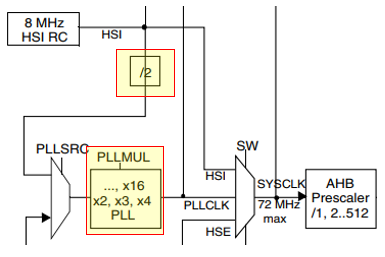
그러나 external crystal 사용에 따른 부품 단가로 인하여 비용 절감(?)을 위해 internal 8Mhz RC Oscillator를 사용하여 HSI (High Speed Internal) crystal output clock frequency mode에서 아래 그림을 참고하면 2 분주 후, 16배 곱하여 maximum 64Mhz system clock를 사용할 수가 있다.
그리고 internal 8Mhz RC Oscillator에 따른 HSI crystral output clock frequency mode의 장단점은 아래와 같다. 단지 main system clock frequency의 accuracy가 저하된다고 하는데, 과연 MCU 시스템에 큰 영향을 끼칠까?
The HSI RC oscillator has the advantage of providing a clock source at low cost (no external components). It also has a faster startup time than the HSE crystal oscillator however, even with calibration the frequency is less accurate than an external crystal oscillator or ceramicresonator.
참고로 STM32F103은 다음과 같이 3가지 종류의 clock source를 제공하고 있다.
- HSI Oscillator clock
- HSE Oscillator clock
- PLL clock
그리고 다음과 같이 maximum clock frequeny가 정의되어 있으므로, 적절하게 선정하여 사용 하도록 하자.
The maximum frequency of the AHB and the APB2 domains is 72 MHz. The maximum allowed frequency of the APB1 domain is 36 MHz.
위의 내용을 토대로 HSI mode를 사용하여 main 64Mhz system clock frequency를 출력하는 예제 코드는 아래와 같다.
void RCC_Configuration_HSI_64Mhz_without_USBclock(void)
{
    ErrorStatus HSIStartUpStatus;

    /* RCC system reset(for debug purpose) */
    RCC_DeInit();

    /* activate HSI (Internal High Speed oscillator) */
    RCC_HSICmd(ENABLE);

    /* Wait until RCC_FLAG_HSIRDY is ready */
    while (RCC_GetFlagStatus(RCC_FLAG_HSIRDY) == RESET);

    /* Enable Prefetch Buffer */
    FLASH_PrefetchBufferCmd(FLASH_PrefetchBuffer_Enable);

    /* Flash 2 wait state */
    FLASH_SetLatency(FLASH_Latency_2);

    /* HCLK = SYSCLK */
    RCC_HCLKConfig(RCC_SYSCLK_Div1);// HCLK = 64 MHz, AHB

    /* PCLK1 = HCLK/2 */
    RCC_PCLK1Config(RCC_HCLK_Div2); // APB1 = 32 MHz

    /* PCLK2 = HCLK */
    RCC_PCLK2Config(RCC_HCLK_Div1); // APB2 = 64 MHz

    /* PLLCLK = (8MHz/2) * 16 = 64MHz */
    RCC_PLLConfig(RCC_PLLSource_HSI_Div2, RCC_PLLMul_16); // 64 MHz

    /* Enable PLL */
    RCC_PLLCmd(ENABLE);

    /* Wait till PLL is ready */
    while(RCC_GetFlagStatus(RCC_FLAG_PLLRDY) == RESET);

    /* Select PLL as system clock source */
    RCC_SYSCLKConfig(RCC_SYSCLKSource_PLLCLK);

    /* Wait till PLL is used as system clock source */
    while(RCC_GetSYSCLKSource() != 0x08);

}
그러나 위의 과정을 거쳐서 USB clock를 사용하게 되면 문제가 발생되는데, 다음과 같이 USB clock를 사용하려면 48Mhz clock이 필요로하다. 그래서 PLL clock은 72Mhz 및 48Mhz의 output clock frequency가 필요하다.
The USB OTG FS 48 MHz clock which is derived from the PLL VCO clock (2 × PLLCLK), followed by a programmable prescaler (divide by 3 or 2).
This selection is made through the OTGFSPRE bit in the RCC_CFGR register.
For proper USB OTG FSoperation, the PLL should be configured to output 72 MHz or 48 MHz.
위의 내용을 토대로 HSI mode를 사용하여 main 48Mhz system clock frequency로 설정하고 48Mhz USB clock 출력하는 예제 코드는 아래와 같다.
void RCC_Configuration_HSI_48Mhz_with_USBclock(void)
{
    ErrorStatus HSIStartUpStatus;

    /* RCC system reset(for debug purpose) */
    RCC_DeInit();

    /* activate HSI (Internal High Speed oscillator) */
    RCC_HSICmd(ENABLE);

    /* Wait until RCC_FLAG_HSIRDY is ready */
    while (RCC_GetFlagStatus(RCC_FLAG_HSIRDY) == RESET);

    /* Enable Prefetch Buffer */
    FLASH_PrefetchBufferCmd(FLASH_PrefetchBuffer_Enable);

    /* Flash 2 wait state */
    FLASH_SetLatency(FLASH_Latency_2);

    /* HCLK = SYSCLK */
    RCC_HCLKConfig(RCC_SYSCLK_Div1);// HCLK = 48 MHz, AHB

    /* PCLK1 = HCLK/2 */
    RCC_PCLK1Config(RCC_HCLK_Div2); // APB1 = 24 MHz

    /* PCLK2 = HCLK */
    RCC_PCLK2Config(RCC_HCLK_Div1); // APB2 = 48 MHz

    /* PLLCLK = (8MHz/2) * 12 = 48MHz */
    RCC_PLLConfig(RCC_PLLSource_HSI_Div2, RCC_PLLMul_12); // 48 MHz

    /* Enable PLL */
    RCC_PLLCmd(ENABLE);

    /* Wait till PLL is ready */
    while(RCC_GetFlagStatus(RCC_FLAG_PLLRDY) == RESET);

    /* Select PLL as system clock source */
    RCC_SYSCLKConfig(RCC_SYSCLKSource_PLLCLK);

    /* Wait till PLL is used as system clock source */
    while(RCC_GetSYSCLKSource() != 0x08);

}
참고로 USB clock 관련 설정은 아래와 같이 code 분리하여 프로그래밍을 하여도 된다.
/*******************************************************************************
* Function Name  : Set_USBClock
* Description    : Configures USB Clock input (48MHz)
* Input          : None.
* Return         : None.
*******************************************************************************/
void Set_USBClock(void)
{
    // Select USBCLK source
    RCC_USBCLKConfig(RCC_USBCLKSource_PLLCLK_Div1);

    // Enable the USB clock
    RCC_APB1PeriphClockCmd(RCC_APB1Periph_USB, ENABLE);
}

/*******************************************************************************
* Function Name  : USB_Interrupts_Config
* Description    : Configures the USB interrupts
* Input          : None.
* Return         : None.
*******************************************************************************/
void USB_Interrupts_Config(void)
{
    NVIC_InitTypeDef NVIC_InitStructure;

    // 2 bit for pre-emption priority, 2 bits for subpriority
    NVIC_PriorityGroupConfig(NVIC_PriorityGroup_2);

    // Enable the USB interrupt
    NVIC_InitStructure.NVIC_IRQChannel = USB_LP_CAN1_RX0_IRQn;
    NVIC_InitStructure.NVIC_IRQChannelPreemptionPriority = 1;
    NVIC_InitStructure.NVIC_IRQChannelSubPriority = 0;
    NVIC_InitStructure.NVIC_IRQChannelCmd = ENABLE;
    NVIC_Init(&NVIC_InitStructure);

    // Enable the USB Wake-up interrupt
    NVIC_InitStructure.NVIC_IRQChannel = USBWakeUp_IRQn;
    NVIC_InitStructure.NVIC_IRQChannelPreemptionPriority = 0;
    NVIC_InitStructure.NVIC_IRQChannelSubPriority = 0;
    NVIC_InitStructure.NVIC_IRQChannelCmd = ENABLE;
    NVIC_Init(&NVIC_InitStructure);

    // Enable the DMA1 Channel1 Interrupt
    NVIC_InitStructure.NVIC_IRQChannel = DMA1_Channel1_IRQn;
    NVIC_InitStructure.NVIC_IRQChannelPreemptionPriority = 0;
    NVIC_InitStructure.NVIC_IRQChannelSubPriority = 0;
    NVIC_InitStructure.NVIC_IRQChannelCmd = ENABLE;
    NVIC_Init(&NVIC_InitStructure);
}

/********************** main.c ***********************/
Set_USBClock();
USB_Interrupts_Config();
USB_Init(); // STM32 USB library at 'usb_init.c'
[부록]
System clock frequency를 48Mhz로 설정하고 나니, 문득 드는 생각이 있는데 GPIO_Speed_2MHz, GPIO_Speed_10MHz, GPIO_Speed_50MHz 의 설정값들이 있는데 GPIO Speed 50Mhz 설정에 따른 GPIO speed 관련 내용을 수집하여 보니, 해당 GPIO speed는 system clock과 관계없이 ARM core의 bus line speed에 대한 의미로 이해하면 된다. 어차피 아래 STM32F103 datasheet 내용을 참조하면 maximum 72Mhz system clock frequency 설정에 따른 maximum GPIO toggling speed는 18Mhz 이다. (GPIO speed 2Mhz의 장점은 EMI noise가 작아진다. 거꾸로 GPIO speed 50Mhz로 설정하면 EMI noise가 높아질 확률이다.)
GPIOs (general-purpose inputs/outputs)
Each of the GPIO pins can be configured by software as output (push-pull or open-drain), as input (with or without pull-up or pull-down) or as peripheral alternate function. Most of the GPIO pins are shared with digital or analog alternate functions. All GPIOs are high currentcapable. The I/Os alternate function configuration can be locked if needed following a specific sequence in order to avoid spurious writing to the I/Os registers. I/Os on APB2 with up to 18 MHz toggling speed.
마지막으로 혹시 몰라서 HSE (High Speed External) crystal output clock frequency mode 관련 예제 코드도 공유한다.
void RCC_Configuration_HSE(void)
{
    ErrorStatus HSEStartUpStatus;

    /* RCC system reset(for debug purpose) */
    RCC_DeInit();

    /* Enable HSE */
    RCC_HSEConfig(RCC_HSE_ON);

    /* Wait till HSE is ready */
    HSEStartUpStatus = RCC_WaitForHSEStartUp();

    if(HSEStartUpStatus == SUCCESS)
    {
        /* Enable Prefetch Buffer */
        FLASH_PrefetchBufferCmd(FLASH_PrefetchBuffer_Enable);

        /* Flash 2 wait state */
        FLASH_SetLatency(FLASH_Latency_2);

        /* HCLK = SYSCLK */
        RCC_HCLKConfig(RCC_SYSCLK_Div1);

        /* PCLK1 = HCLK/2 */
        RCC_PCLK1Config(RCC_HCLK_Div2);

        /* PCLK2 = HCLK */
        RCC_PCLK2Config(RCC_HCLK_Div1);

        /* ADCCLK = PCLK2/4 */
        RCC_ADCCLKConfig(RCC_PCLK2_Div6);

        /* PLLCLK = 12MHz * 6 = 72 MHz */
        RCC_PLLConfig(RCC_PLLSource_HSE_Div1, RCC_PLLMul_6);

        /* Enable PLL */
        RCC_PLLCmd(ENABLE);

        /* Wait till PLL is ready */
        while(RCC_GetFlagStatus(RCC_FLAG_PLLRDY) == RESET);

        /* Select PLL as system clock source */
        RCC_SYSCLKConfig(RCC_SYSCLKSource_PLLCLK);

        /* Wait till PLL is used as system clock source */
        while(RCC_GetSYSCLKSource() != 0x08);
    }
}
'Engineer > 소프트웨어 정보' 카테고리의 다른 글
| [STM32] Interrupt 사용하기 (0) | 2020.06.24 |
|---|---|
| 임의 길이의 숫자 데이터를 signed extend number로 표현 (0) | 2020.05.19 |
| [STM32F10x] hardware I2C example code (0) | 2020.02.04 |
| [STM32F10x] software I2C example code (2) | 2020.02.04 |
| STM32 ARM series 이클립스(Eclipse) 내 GCC 컴파일 개발 환경 구축 (0) | 2020.01.29 |