반응형


반응형
STM32F103 series MCU의 hardware SPI interface를 사용하기 위해서 아래와 같이 GPIO 설정이 필요로 한다.
#define GPIO_HW_SPI            GPIOA
#define GPIO_HW_SPI_CS                  GPIO_Pin_4    // NSS PIN
#define GPIO_HW_SPI_SCLK                GPIO_Pin_5    // Clock
#define GPIO_HW_SPI_MISO                GPIO_Pin_6    // Master Input to Slave Output
#define GPIO_HW_SPI_MOSI                GPIO_Pin_7    // Master Output to Slave Input

#define HW_SPI_READ_BIT			0x80
#define HW_SPI_WRITE_BIT		0x00

/* Select hardware SPI: Chip Select pin low  */
#define HW_SPI_CS_LOW()       GPIO_ResetBits(GPIO_HW_SPI, GPIO_HW_SPI_CS)
/* Deselect hardware SPI: Chip Select pin high */
#define HW_SPI_CS_HIGH()      GPIO_SetBits(GPIO_HW_SPI, GPIO_HW_SPI_CS)

void MXM1160_HW_SPI_GPIO_Init(void){

    SPI_InitTypeDef  SPI_InitStructure;
    GPIO_InitTypeDef GPIO_InitStructure;

    /* Enable SPI1 and GPIO clocks */
    RCC_APB2PeriphClockCmd(RCC_APB2Periph_GPIOA | RCC_APB2Periph_SPI1, ENABLE);

    /* Configure SPI1 pins: SCK, MISO and MOSI */
    GPIO_InitStructure.GPIO_Pin   =  GPIO_HW_SPI_SCLK | GPIO_HW_SPI_MOSI | GPIO_HW_SPI_MISO;
    GPIO_InitStructure.GPIO_Speed = GPIO_Speed_50MHz;
    GPIO_InitStructure.GPIO_Mode  = GPIO_Mode_AF_PP;
    GPIO_Init(GPIO_HW_SPI, &GPIO_InitStructure);

    /* Configure I/O for the sensor select */
    GPIO_InitStructure.GPIO_Pin   =  GPIO_HW_SPI_CS;
    GPIO_InitStructure.GPIO_Speed = GPIO_Speed_50MHz;
    GPIO_InitStructure.GPIO_Mode  = GPIO_Mode_Out_PP;
    GPIO_Init(GPIO_HW_SPI, &GPIO_InitStructure);

    /* Deselect the hardware SPI : Sensor Select high */
    HW_SPI_CS_HIGH();

    /* SPI1 configuration */
    SPI_InitStructure.SPI_Direction = SPI_Direction_2Lines_FullDuplex;
    SPI_InitStructure.SPI_Mode = SPI_Mode_Master;
    SPI_InitStructure.SPI_DataSize = SPI_DataSize_8b;
    SPI_InitStructure.SPI_CPOL = SPI_CPOL_High;
    SPI_InitStructure.SPI_CPHA = SPI_CPHA_2Edge;
    SPI_InitStructure.SPI_NSS = SPI_NSS_Soft;
    SPI_InitStructure.SPI_BaudRatePrescaler = SPI_BaudRatePrescaler_16;
    SPI_InitStructure.SPI_FirstBit = SPI_FirstBit_MSB;
    SPI_InitStructure.SPI_CRCPolynomial = 1;
    SPI_Init(SPI1, &SPI_InitStructure);

    /* Enable SPI1  */
    SPI_Cmd(SPI1, ENABLE);
}
위의 'SPI_InitStructure.SPI_CPOL"와 'SPI_InitStructure.SPI_CPHA'는 사용자 개발 환경과 SPI 통신을 사용하는 slave chip의 통신 모드의 Clock Plarity (CPOL), Clock Phase (CPHA)의 의해 결정되므로 개별적으로 확인하길 바란다.
그 다음에 SPI 통신은 양방향 통신이기 때문에 Read / Write command에 따라 dummy byte 등 적절한 array index 관리를 해주면 된다.
void  HW_SPI_Multi_TXRX(uint8_t Cmd, uint8_t addr, uint8_t count, uint8_t  *pData)
{
    uint8_t BufferSize = count;
    uint8_t SPI_Dummy_Tx = 0x00;
    uint8_t SPI_Dummy_Rx = 0x00;

    // Check the Command mode and Address
    SPI_Dummy_Tx = Cmd | addr;

    HW_SPI_CS_LOW();

    /* Wait for SPIy Tx buffer empty */
    while (SPI_I2S_GetFlagStatus(SPI1, SPI_I2S_FLAG_TXE) == RESET);
    /* Send SPIy data */
    SPI_I2S_SendData(SPI1, SPI_Dummy_Tx);

    /* Wait for SPIy data reception */
    while (SPI_I2S_GetFlagStatus(SPI1, SPI_I2S_FLAG_RXNE) == RESET);
    /* Read SPIy received data */
    SPI_Dummy_Rx = SPI_I2S_ReceiveData(SPI1);

    while(count>1){

        /* Wait for SPIy Tx buffer empty */
        while (SPI_I2S_GetFlagStatus(SPI1, SPI_I2S_FLAG_TXE) == RESET);
        /* Send SPIy data */
        SPI_I2S_SendData(SPI1, pData[BufferSize-count]);

        /* Wait for SPIy data reception */
        while (SPI_I2S_GetFlagStatus(SPI1, SPI_I2S_FLAG_RXNE) == RESET);
        /* Read SPIy received data */
        if ( Cmd == HW_SPI_READ_BIT ){
            pData[BufferSize-count] = SPI_I2S_ReceiveData(SPI1);
        }
        else{
            SPI_Dummy_Rx = SPI_I2S_ReceiveData(SPI1);
        }
        count--;
    }

    /* Wait for SPIy Tx buffer empty */
    while (SPI_I2S_GetFlagStatus(SPI1, SPI_I2S_FLAG_TXE) == RESET);
    /* Send SPIy data */
    SPI_I2S_SendData(SPI1, pData[BufferSize-count]);

    /* Wait for SPIy data reception */
    while (SPI_I2S_GetFlagStatus(SPI1, SPI_I2S_FLAG_RXNE) == RESET);
    /* Read SPIy received data */
    if ( Cmd == HW_SPI_READ_BIT ){
        pData[BufferSize-count] = SPI_I2S_ReceiveData(SPI1);
    }
    else{
        SPI_Dummy_Rx = SPI_I2S_ReceiveData(SPI1);
    }

    HW_SPI_CS_HIGH();
}
마지막으로 SPI 통신의 waveform grpah 관련 자료는 구글링을 하면 되므로, 검색 스킬을 발휘하길 바란다.
끝.
| ISE Design Suite for Windows 10 - 14.7 설치 & Install (0) | 2022.11.03 |
|---|---|
| CRC example code [TE HTU21D datasheet] (0) | 2021.02.15 |
| [STM32F103] delay_us 함수 (0) | 2020.07.24 |
| [STM32] Interrupt 사용하기 (0) | 2020.06.24 |
| 임의 길이의 숫자 데이터를 signed extend number로 표현 (0) | 2020.05.19 |
본인은 STM32F103 시리즈 MCU를 사용하고 있으며, Interrupt 기능을 사용하기 위해 GPIOA Pin 4번을 이용하여 인터럽트 관련 설정 코드를 아래와 같이 하였다.
void STM32_Interrupt_initial(void)
{
	RCC_APB2PeriphClockCmd(RCC_APB2Periph_GPIOA  | RCC_APB2Periph_AFIO, ENABLE);

	// GPIOA Pin 4 Interrupt
	GPIO_InitStructure.GPIO_Pin = GPIO_Pin_4;
	GPIO_InitStructure.GPIO_Mode = GPIO_Mode_IN_FLOATING;
	GPIO_InitStructure.GPIO_Speed = GPIO_Speed_50MHz;
	GPIO_Init(GPIOA, &GPIO_InitStructure);

	// Connect EXTI Line to gpio pin
	GPIO_EXTILineConfig(GPIO_PortSourceGPIOA, GPIO_PinSource4);

	// Configure EXTI Line to generate an interrupt
	EXTI_InitStructure.EXTI_Line    = EXTI_Line4;
	EXTI_InitStructure.EXTI_Mode    = EXTI_Mode_Interrupt;
	EXTI_InitStructure.EXTI_Trigger = EXTI_Trigger_Falling;
	EXTI_InitStructure.EXTI_LineCmd = ENABLE;
	EXTI_Init(&EXTI_InitStructure);

	// Configure the NVIC Preemption Priority Bits
	NVIC_PriorityGroupConfig(NVIC_PriorityGroup_0);

	// Enable the EXTI4 Interrupt
	NVIC_InitStructure.NVIC_IRQChannel = EXTI4_IRQn;
	NVIC_InitStructure.NVIC_IRQChannelPreemptionPriority = 0;
	NVIC_InitStructure.NVIC_IRQChannelSubPriority = 0;
	NVIC_InitStructure.NVIC_IRQChannelCmd = ENABLE;
	NVIC_Init(&NVIC_InitStructure);
}
EXTI 및 NVIC 관련 설정은 구글링을 하면 많은 자료가 검색 되므로, 굳이 설명을 하지 않기로 한다.
참고로 "EXTI1_IRQHandler" ~ "EXTI4_IRQHandler", "EXTI9_5_IRQHandler", "EXTI15_10_IRQHandler"의 IRQ 핸들러를 설정할 수 있는데, Pin0 부터 Pin4까지는 지정된 IRQHandler를 사용해야 하고, Pin5 부터 Pin9는 EXTI9_5_IRQHandler를 사용해야 한다. 마찬가지로 Pin10 부터 Pin15는 EXTI15_10_IRQHandler를사용해야한다.
/*******************************************************************************
* Function Name  : EXTI4_IRQHandler
* Description    : This function handles External interrupt Line 4 request.
* Input          : None
* Output         : None
* Return         : None
*******************************************************************************/
void EXTI4_IRQHandler(void)
{
	if(EXTI_GetITStatus(GPIO_Pin_4) != RESET)
	{
		printf("Interrupt OK\n");

		// Clear the Interrupt EXTI line pending bit
		EXTI_ClearITPendingBit(GPIO_Pin_4);
	}
}
이렇게 하여, 해당 GPIO Pin에 Failling Signal을 전달하면, 아래와 같이 debug message가 나타난다.
| [STM32] hardware SPI example code (0) | 2020.09.09 |
|---|---|
| [STM32F103] delay_us 함수 (0) | 2020.07.24 |
| 임의 길이의 숫자 데이터를 signed extend number로 표현 (0) | 2020.05.19 |
| [STM32F103 Series] HSI clock 사용 (내부 8Mhz to 64Mhz) (0) | 2020.02.18 |
| [STM32F10x] hardware I2C example code (0) | 2020.02.04 |
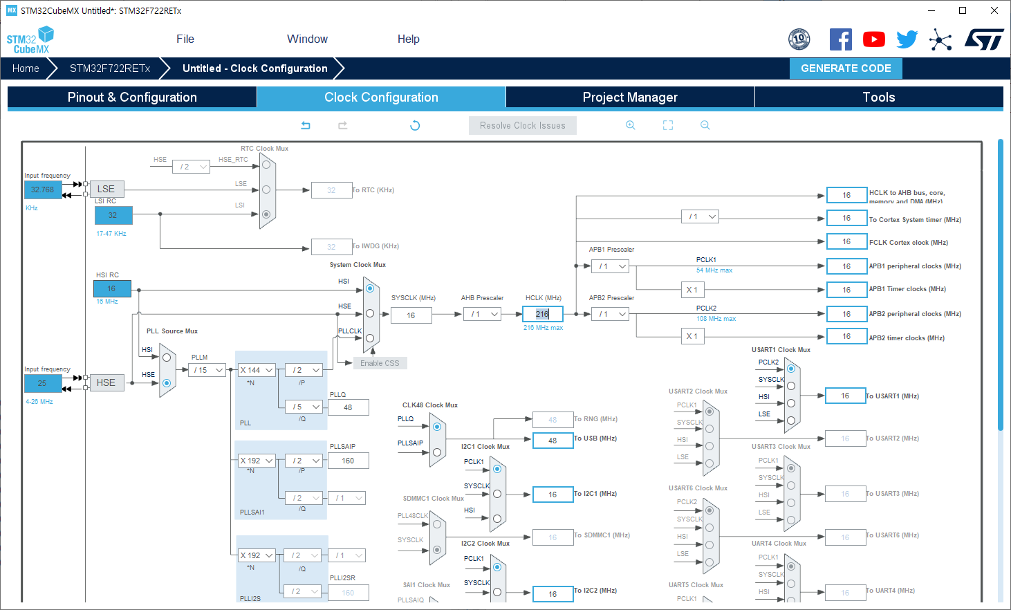
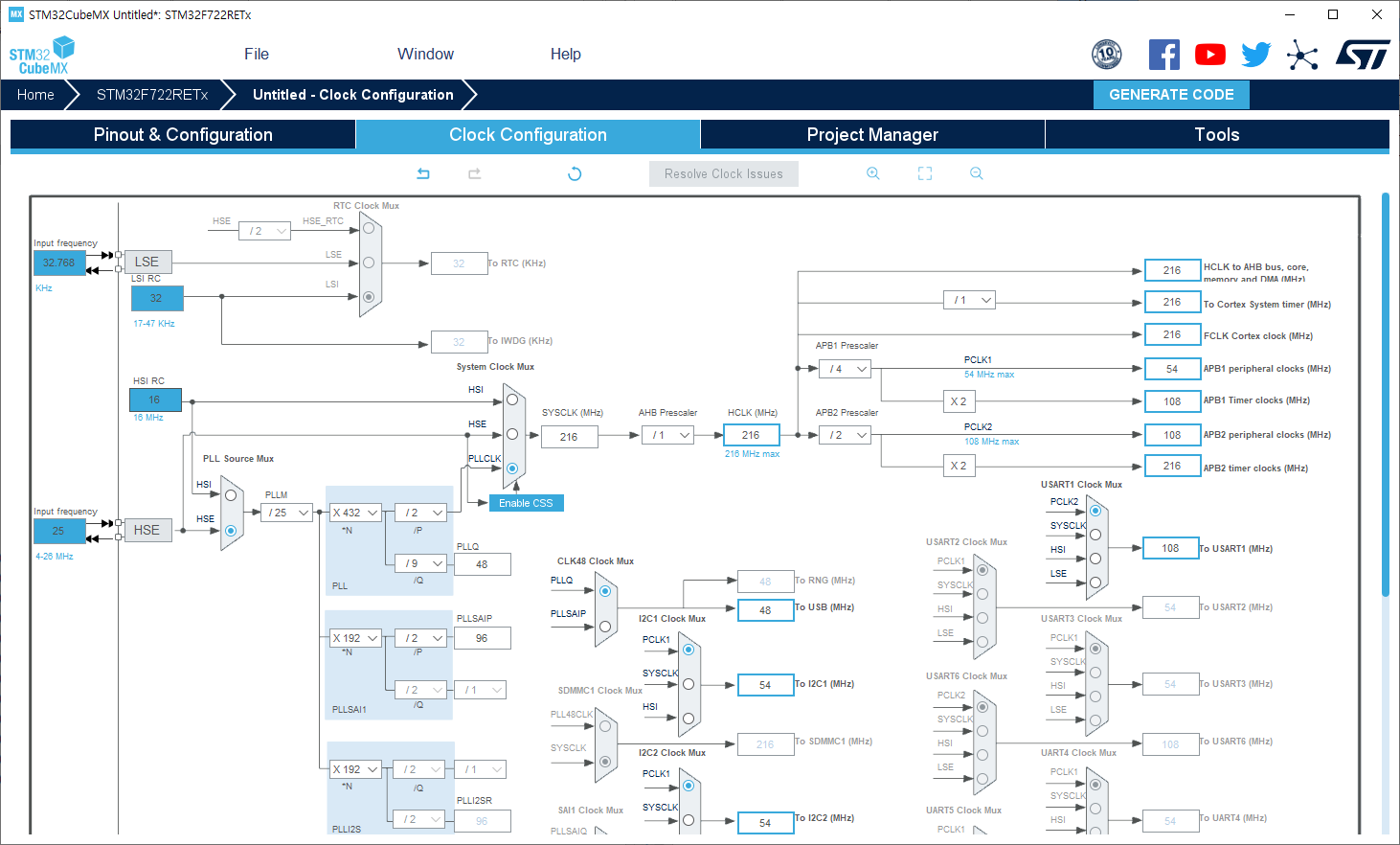
STM32F103 series로 maximum 72Mhz system clock를 사용하려면 외부 12Mhz oscillator를 실장하여 HSE (High Speed External) crystal output clock frequency mode로 PLL multiplication factor 제어하여 6배 (PLL input clock x 6) 곱하여 72Mhz PLLCLK source로 사용하고 있었다.
그러나 external crystal 사용에 따른 부품 단가로 인하여 비용 절감(?)을 위해 internal 8Mhz RC Oscillator를 사용하여 HSI (High Speed Internal) crystal output clock frequency mode에서 아래 그림을 참고하면 2 분주 후, 16배 곱하여 maximum 64Mhz system clock를 사용할 수가 있다.
그리고 internal 8Mhz RC Oscillator에 따른 HSI crystral output clock frequency mode의 장단점은 아래와 같다. 단지 main system clock frequency의 accuracy가 저하된다고 하는데, 과연 MCU 시스템에 큰 영향을 끼칠까?
The HSI RC oscillator has the advantage of providing a clock source at low cost (no external components). It also has a faster startup time than the HSE crystal oscillator however, even with calibration the frequency is less accurate than an external crystal oscillator or ceramicresonator.
참고로 STM32F103은 다음과 같이 3가지 종류의 clock source를 제공하고 있다.
- HSI Oscillator clock
- HSE Oscillator clock
- PLL clock
그리고 다음과 같이 maximum clock frequeny가 정의되어 있으므로, 적절하게 선정하여 사용 하도록 하자.
The maximum frequency of the AHB and the APB2 domains is 72 MHz. The maximum allowed frequency of the APB1 domain is 36 MHz.
위의 내용을 토대로 HSI mode를 사용하여 main 64Mhz system clock frequency를 출력하는 예제 코드는 아래와 같다.
void RCC_Configuration_HSI_64Mhz_without_USBclock(void)
{
    ErrorStatus HSIStartUpStatus;

    /* RCC system reset(for debug purpose) */
    RCC_DeInit();

    /* activate HSI (Internal High Speed oscillator) */
    RCC_HSICmd(ENABLE);

    /* Wait until RCC_FLAG_HSIRDY is ready */
    while (RCC_GetFlagStatus(RCC_FLAG_HSIRDY) == RESET);

    /* Enable Prefetch Buffer */
    FLASH_PrefetchBufferCmd(FLASH_PrefetchBuffer_Enable);

    /* Flash 2 wait state */
    FLASH_SetLatency(FLASH_Latency_2);

    /* HCLK = SYSCLK */
    RCC_HCLKConfig(RCC_SYSCLK_Div1);// HCLK = 64 MHz, AHB

    /* PCLK1 = HCLK/2 */
    RCC_PCLK1Config(RCC_HCLK_Div2); // APB1 = 32 MHz

    /* PCLK2 = HCLK */
    RCC_PCLK2Config(RCC_HCLK_Div1); // APB2 = 64 MHz

    /* PLLCLK = (8MHz/2) * 16 = 64MHz */
    RCC_PLLConfig(RCC_PLLSource_HSI_Div2, RCC_PLLMul_16); // 64 MHz

    /* Enable PLL */
    RCC_PLLCmd(ENABLE);

    /* Wait till PLL is ready */
    while(RCC_GetFlagStatus(RCC_FLAG_PLLRDY) == RESET);

    /* Select PLL as system clock source */
    RCC_SYSCLKConfig(RCC_SYSCLKSource_PLLCLK);

    /* Wait till PLL is used as system clock source */
    while(RCC_GetSYSCLKSource() != 0x08);

}
그러나 위의 과정을 거쳐서 USB clock를 사용하게 되면 문제가 발생되는데, 다음과 같이 USB clock를 사용하려면 48Mhz clock이 필요로하다. 그래서 PLL clock은 72Mhz 및 48Mhz의 output clock frequency가 필요하다.
The USB OTG FS 48 MHz clock which is derived from the PLL VCO clock (2 × PLLCLK), followed by a programmable prescaler (divide by 3 or 2).
This selection is made through the OTGFSPRE bit in the RCC_CFGR register.
For proper USB OTG FSoperation, the PLL should be configured to output 72 MHz or 48 MHz.
위의 내용을 토대로 HSI mode를 사용하여 main 48Mhz system clock frequency로 설정하고 48Mhz USB clock 출력하는 예제 코드는 아래와 같다.
void RCC_Configuration_HSI_48Mhz_with_USBclock(void)
{
    ErrorStatus HSIStartUpStatus;

    /* RCC system reset(for debug purpose) */
    RCC_DeInit();

    /* activate HSI (Internal High Speed oscillator) */
    RCC_HSICmd(ENABLE);

    /* Wait until RCC_FLAG_HSIRDY is ready */
    while (RCC_GetFlagStatus(RCC_FLAG_HSIRDY) == RESET);

    /* Enable Prefetch Buffer */
    FLASH_PrefetchBufferCmd(FLASH_PrefetchBuffer_Enable);

    /* Flash 2 wait state */
    FLASH_SetLatency(FLASH_Latency_2);

    /* HCLK = SYSCLK */
    RCC_HCLKConfig(RCC_SYSCLK_Div1);// HCLK = 48 MHz, AHB

    /* PCLK1 = HCLK/2 */
    RCC_PCLK1Config(RCC_HCLK_Div2); // APB1 = 24 MHz

    /* PCLK2 = HCLK */
    RCC_PCLK2Config(RCC_HCLK_Div1); // APB2 = 48 MHz

    /* PLLCLK = (8MHz/2) * 12 = 48MHz */
    RCC_PLLConfig(RCC_PLLSource_HSI_Div2, RCC_PLLMul_12); // 48 MHz

    /* Enable PLL */
    RCC_PLLCmd(ENABLE);

    /* Wait till PLL is ready */
    while(RCC_GetFlagStatus(RCC_FLAG_PLLRDY) == RESET);

    /* Select PLL as system clock source */
    RCC_SYSCLKConfig(RCC_SYSCLKSource_PLLCLK);

    /* Wait till PLL is used as system clock source */
    while(RCC_GetSYSCLKSource() != 0x08);

}
참고로 USB clock 관련 설정은 아래와 같이 code 분리하여 프로그래밍을 하여도 된다.
/*******************************************************************************
* Function Name  : Set_USBClock
* Description    : Configures USB Clock input (48MHz)
* Input          : None.
* Return         : None.
*******************************************************************************/
void Set_USBClock(void)
{
    // Select USBCLK source
    RCC_USBCLKConfig(RCC_USBCLKSource_PLLCLK_Div1);

    // Enable the USB clock
    RCC_APB1PeriphClockCmd(RCC_APB1Periph_USB, ENABLE);
}

/*******************************************************************************
* Function Name  : USB_Interrupts_Config
* Description    : Configures the USB interrupts
* Input          : None.
* Return         : None.
*******************************************************************************/
void USB_Interrupts_Config(void)
{
    NVIC_InitTypeDef NVIC_InitStructure;

    // 2 bit for pre-emption priority, 2 bits for subpriority
    NVIC_PriorityGroupConfig(NVIC_PriorityGroup_2);

    // Enable the USB interrupt
    NVIC_InitStructure.NVIC_IRQChannel = USB_LP_CAN1_RX0_IRQn;
    NVIC_InitStructure.NVIC_IRQChannelPreemptionPriority = 1;
    NVIC_InitStructure.NVIC_IRQChannelSubPriority = 0;
    NVIC_InitStructure.NVIC_IRQChannelCmd = ENABLE;
    NVIC_Init(&NVIC_InitStructure);

    // Enable the USB Wake-up interrupt
    NVIC_InitStructure.NVIC_IRQChannel = USBWakeUp_IRQn;
    NVIC_InitStructure.NVIC_IRQChannelPreemptionPriority = 0;
    NVIC_InitStructure.NVIC_IRQChannelSubPriority = 0;
    NVIC_InitStructure.NVIC_IRQChannelCmd = ENABLE;
    NVIC_Init(&NVIC_InitStructure);

    // Enable the DMA1 Channel1 Interrupt
    NVIC_InitStructure.NVIC_IRQChannel = DMA1_Channel1_IRQn;
    NVIC_InitStructure.NVIC_IRQChannelPreemptionPriority = 0;
    NVIC_InitStructure.NVIC_IRQChannelSubPriority = 0;
    NVIC_InitStructure.NVIC_IRQChannelCmd = ENABLE;
    NVIC_Init(&NVIC_InitStructure);
}

/********************** main.c ***********************/
Set_USBClock();
USB_Interrupts_Config();
USB_Init(); // STM32 USB library at 'usb_init.c'
[부록]
System clock frequency를 48Mhz로 설정하고 나니, 문득 드는 생각이 있는데 GPIO_Speed_2MHz, GPIO_Speed_10MHz, GPIO_Speed_50MHz 의 설정값들이 있는데 GPIO Speed 50Mhz 설정에 따른 GPIO speed 관련 내용을 수집하여 보니, 해당 GPIO speed는 system clock과 관계없이 ARM core의 bus line speed에 대한 의미로 이해하면 된다. 어차피 아래 STM32F103 datasheet 내용을 참조하면 maximum 72Mhz system clock frequency 설정에 따른 maximum GPIO toggling speed는 18Mhz 이다. (GPIO speed 2Mhz의 장점은 EMI noise가 작아진다. 거꾸로 GPIO speed 50Mhz로 설정하면 EMI noise가 높아질 확률이다.)
GPIOs (general-purpose inputs/outputs)
Each of the GPIO pins can be configured by software as output (push-pull or open-drain), as input (with or without pull-up or pull-down) or as peripheral alternate function. Most of the GPIO pins are shared with digital or analog alternate functions. All GPIOs are high currentcapable. The I/Os alternate function configuration can be locked if needed following a specific sequence in order to avoid spurious writing to the I/Os registers. I/Os on APB2 with up to 18 MHz toggling speed.
마지막으로 혹시 몰라서 HSE (High Speed External) crystal output clock frequency mode 관련 예제 코드도 공유한다.
void RCC_Configuration_HSE(void)
{
    ErrorStatus HSEStartUpStatus;

    /* RCC system reset(for debug purpose) */
    RCC_DeInit();

    /* Enable HSE */
    RCC_HSEConfig(RCC_HSE_ON);

    /* Wait till HSE is ready */
    HSEStartUpStatus = RCC_WaitForHSEStartUp();

    if(HSEStartUpStatus == SUCCESS)
    {
        /* Enable Prefetch Buffer */
        FLASH_PrefetchBufferCmd(FLASH_PrefetchBuffer_Enable);

        /* Flash 2 wait state */
        FLASH_SetLatency(FLASH_Latency_2);

        /* HCLK = SYSCLK */
        RCC_HCLKConfig(RCC_SYSCLK_Div1);

        /* PCLK1 = HCLK/2 */
        RCC_PCLK1Config(RCC_HCLK_Div2);

        /* PCLK2 = HCLK */
        RCC_PCLK2Config(RCC_HCLK_Div1);

        /* ADCCLK = PCLK2/4 */
        RCC_ADCCLKConfig(RCC_PCLK2_Div6);

        /* PLLCLK = 12MHz * 6 = 72 MHz */
        RCC_PLLConfig(RCC_PLLSource_HSE_Div1, RCC_PLLMul_6);

        /* Enable PLL */
        RCC_PLLCmd(ENABLE);

        /* Wait till PLL is ready */
        while(RCC_GetFlagStatus(RCC_FLAG_PLLRDY) == RESET);

        /* Select PLL as system clock source */
        RCC_SYSCLKConfig(RCC_SYSCLKSource_PLLCLK);

        /* Wait till PLL is used as system clock source */
        while(RCC_GetSYSCLKSource() != 0x08);
    }
}
| [STM32] Interrupt 사용하기 (0) | 2020.06.24 |
|---|---|
| 임의 길이의 숫자 데이터를 signed extend number로 표현 (0) | 2020.05.19 |
| [STM32F10x] hardware I2C example code (0) | 2020.02.04 |
| [STM32F10x] software I2C example code (2) | 2020.02.04 |
| STM32 ARM series 이클립스(Eclipse) 내 GCC 컴파일 개발 환경 구축 (0) | 2020.01.29 |
STM32F10x series MCU를 사용하면서 제공되는 stm32f10x_i2c.h / stm32f10x_i2c.c 관련 STM32 library를 사용한 hardware I2C example code를 공유한다.
# i2c_hw.h
#ifndef __I2C_HW_H
#define __I2C_HW_H

/* includes */
#include "stm32f10x.h"
#include "hw_config.h"
/* defines */
/* functions */
void HW_I2C_master_initial(void);

uint8_t HW_I2C_Read(I2C_TypeDef* I2Cx, uint8_t DeviceAddr, uint8_t RegisterAddr, uint16_t NumByteToRead, uint8_t* pBuffer);
uint8_t HW_I2C_Write(I2C_TypeDef* I2Cx, uint8_t DeviceAddr, uint8_t RegisterAddr, uint16_t NumByteToWrite, uint8_t* pBuffer);
uint8_t I2C_Check_SlaveAddr(I2C_TypeDef* I2Cx, uint8_t DeviceAddr);

uint8_t HW_I2C_UTIL_Write(I2C_TypeDef* I2Cx, uint8_t DeviceAddr, uint8_t RegisterAddr, uint8_t pBuffer);
uint8_t HW_I2C_UTIL_Read(I2C_TypeDef* I2Cx, uint8_t DeviceAddr, uint8_t RegisterAddr);
void HW_I2C_UTIL_Write_Multi(I2C_TypeDef* I2Cx, uint8_t DeviceAddr, uint8_t RegisterAddr, uint16_t NumByteToWrite, uint8_t* pBuffer);
uint8_t HW_I2C_UTIL_Read_Multi(I2C_TypeDef* I2Cx, uint8_t DeviceAddr, uint8_t RegisterAddr, uint8_t ReadCount, uint8_t (*pReadData));
uint8_t HW_I2C_UTIL_Check_SlaveAddr(I2C_TypeDef* I2Cx);

#endif  /* __I2C_HW_H */
# i2c_hw.c
#include "i2c_hw.h"

#define MAX_COMMUNICATION_FREQ   ((uint32_t) 400000)	// 100khz
#define FLAG_TIMEOUT             ((uint32_t)0x1000)
#define LONG_TIMEOUT             ((uint32_t)(10 * FLAG_TIMEOUT))

#define GPIO_I2C_HW        GPIOB

#define GPIO_I2C1_SCL	GPIO_Pin_6
#define GPIO_I2C1_SDA	GPIO_Pin_7
#define GPIO_I2C2_SCL	GPIO_Pin_10
#define GPIO_I2C2_SDA	GPIO_Pin_11

__IO uint32_t  UTIL_Timeout = LONG_TIMEOUT;
__IO uint16_t  UTIL_Address = 0;

void HW_I2C_master_initial(void)
{
	I2C_InitTypeDef 	I2C_InitStructure;
	GPIO_InitTypeDef	GPIO_InitStructure;

	// I2C_SCL_GPIO_CLK and I2C_SDA_GPIO_CLK Periph clock enable
	RCC_APB2PeriphClockCmd(RCC_APB2Periph_GPIOB, ENABLE);
	// I2C Periph clock enable
	RCC_APB1PeriphClockCmd(RCC_APB1Periph_I2C1, ENABLE);
	RCC_APB1PeriphClockCmd(RCC_APB1Periph_I2C2, ENABLE);

	// Configure I2C pins: SCL , SDA
	GPIO_InitStructure.GPIO_Pin = GPIO_I2C1_SCL | GPIO_I2C1_SDA | GPIO_I2C2_SCL | GPIO_I2C2_SDA;;
	GPIO_InitStructure.GPIO_Speed = GPIO_Speed_50MHz;
	GPIO_InitStructure.GPIO_Mode = GPIO_Mode_AF_OD;
	GPIO_Init(GPIO_I2C_HW, &GPIO_InitStructure);

	// Free all used resources
	I2C_DeInit(I2C1);
	I2C_DeInit(I2C2);

	I2C_InitStructure.I2C_Mode = I2C_Mode_I2C;
	I2C_InitStructure.I2C_DutyCycle = I2C_DutyCycle_2;
	I2C_InitStructure.I2C_OwnAddress1 = 0x00;
	I2C_InitStructure.I2C_Ack = I2C_Ack_Enable;
	I2C_InitStructure.I2C_AcknowledgedAddress = I2C_AcknowledgedAddress_7bit;
	I2C_InitStructure.I2C_ClockSpeed = MAX_COMMUNICATION_FREQ;
	I2C_Init(I2C1, &I2C_InitStructure);
	I2C_Init(I2C2, &I2C_InitStructure);

	I2C_Cmd(I2C1, ENABLE);
	I2C_Cmd(I2C2, ENABLE);
}

uint8_t HW_I2C_Read(I2C_TypeDef* I2Cx, uint8_t DeviceAddr, uint8_t RegisterAddr, uint16_t NumByteToRead, uint8_t* pBuffer)
{
  __IO uint32_t UTIL_Timeout = LONG_TIMEOUT;
  __IO uint32_t temp;

  (void)(temp);

restart:

  UTIL_Timeout = LONG_TIMEOUT;
/* Send START condition */
  I2C_GenerateSTART(I2Cx, ENABLE);
  /* Test on EV5 and clear it */
  while (!I2C_CheckEvent(I2Cx, I2C_EVENT_MASTER_MODE_SELECT))
  {
    if (UTIL_Timeout-- == 0)
      return ERROR;
  }

  UTIL_Timeout = LONG_TIMEOUT;
  /* Send slave address for read */
  I2C_Send7bitAddress(I2Cx, DeviceAddr, I2C_Direction_Transmitter);

  while (!I2C_CheckEvent(I2Cx,I2C_EVENT_MASTER_TRANSMITTER_MODE_SELECTED))
  {
    if (UTIL_Timeout-- == 0)
    {
      I2C_ClearFlag(I2Cx,I2C_FLAG_BUSY|I2C_FLAG_AF);
      goto restart;
    }
  }
  /* Clear EV6 by setting again the PE bit */
  I2C_Cmd(I2Cx, ENABLE);

  I2C_SendData(I2Cx, RegisterAddr);

  /* Test on EV8 and clear it */
  UTIL_Timeout = LONG_TIMEOUT;
  while (!I2C_CheckEvent(I2Cx, I2C_EVENT_MASTER_BYTE_TRANSMITTED))
  {
    if (UTIL_Timeout-- == 0)
     return ERROR;
  }

  if (NumByteToRead == 0x01)
  {
    restart3:
    /* Send START condition */
    I2C_GenerateSTART(I2Cx, ENABLE);
    while (!I2C_CheckEvent(I2Cx, I2C_EVENT_MASTER_MODE_SELECT));
    /* Send Slave address for read */
    I2C_Send7bitAddress(I2Cx, DeviceAddr, I2C_Direction_Receiver);
    /* Wait until ADDR is set */
    UTIL_Timeout = LONG_TIMEOUT;
    while (!I2C_GetFlagStatus(I2Cx, I2C_FLAG_ADDR))
    {
      if (UTIL_Timeout-- == 0)
      {
        I2C_ClearFlag(I2Cx,I2C_FLAG_BUSY|I2C_FLAG_AF);
        goto restart3;
      }
    }
    /* Clear ACK */
    I2C_AcknowledgeConfig(I2Cx, DISABLE);
    __disable_irq();
    /* Clear ADDR flag */
    temp = I2Cx->SR2;
    /* Program the STOP */
    I2C_GenerateSTOP(I2Cx, ENABLE);
    __enable_irq();
    while ((I2C_GetLastEvent(I2Cx) & 0x0040) != 0x000040); /* Poll on RxNE */
    /* Read the data */
    *pBuffer = I2C_ReceiveData(I2Cx);
    /* Make sure that the STOP bit is cleared by Hardware before CR1 write access */
    while ((I2Cx->CR1&0x200) == 0x200);
    /* Enable Acknowledgement to be ready for another reception */
    I2C_AcknowledgeConfig(I2Cx, ENABLE);

    return SUCCESS;
  }
  else
    if(NumByteToRead == 0x02)
    {
      restart4:
      /* Send START condition */
      I2C_GenerateSTART(I2Cx, ENABLE);
      while (!I2C_CheckEvent(I2Cx, I2C_EVENT_MASTER_MODE_SELECT));
      /* Send EEPROM address for read */
      I2C_Send7bitAddress(I2Cx, DeviceAddr, I2C_Direction_Receiver);
      I2Cx->CR1 = 0xC01; /* ACK=1; POS =1 */
      UTIL_Timeout = LONG_TIMEOUT;
      while (!I2C_GetFlagStatus(I2Cx, I2C_FLAG_ADDR))
      {
        if (UTIL_Timeout-- == 0)
        {
          I2C_ClearFlag(I2Cx,I2C_FLAG_BUSY|I2C_FLAG_AF);
          goto restart4;
        }
      }
      __disable_irq();
      /* Clear ADDR */
      temp = I2Cx->SR2;
      /* Disable ACK */
      I2C_AcknowledgeConfig(I2Cx, DISABLE);
      __enable_irq();
      while ((I2C_GetLastEvent(I2Cx) & 0x0004) != 0x00004); /* Poll on BTF */

       __disable_irq();
      /* Program the STOP */
      I2C_GenerateSTOP(I2Cx, ENABLE);
      /* Read first data */
      *pBuffer = I2Cx->DR;
      pBuffer++;
      /* Read second data */
      *pBuffer = I2Cx->DR;
      __enable_irq();
      I2Cx->CR1 = 0x0401; /* POS = 0, ACK = 1, PE = 1 */

      return SUCCESS;
    }
  else
  {
restart2:
    UTIL_Timeout = LONG_TIMEOUT;
    /* Send START condition */
    I2C_GenerateSTART(I2Cx, ENABLE);
    /* Test on EV5 and clear it */
    while (!I2C_CheckEvent(I2Cx, I2C_EVENT_MASTER_MODE_SELECT))
    {
      if (UTIL_Timeout-- == 0) return ERROR;
    }
    UTIL_Timeout = LONG_TIMEOUT;
    /* Send slave address for read */
    I2C_Send7bitAddress(I2Cx,  DeviceAddr, I2C_Direction_Receiver);
    while (!I2C_CheckEvent(I2Cx, I2C_EVENT_MASTER_RECEIVER_MODE_SELECTED))
    {

      if (UTIL_Timeout-- == 0)
      {
        I2C_ClearFlag(I2Cx,I2C_FLAG_BUSY|I2C_FLAG_AF);
        goto restart2;
      }
    }

    /* While there is data to be read; here the safe procedure is implemented */
    while (NumByteToRead)
    {

      if (NumByteToRead != 3) /* Receive bytes from first byte until byte N-3 */
      {
        while ((I2C_GetLastEvent(I2Cx) & 0x00004) != 0x000004); /* Poll on BTF */
        /* Read data */
        *pBuffer = I2C_ReceiveData(I2Cx);
        pBuffer++;
        /* Decrement the read bytes counter */
        NumByteToRead--;
      }

      if (NumByteToRead == 3)  /* it remains to read three data: data N-2, data N-1, Data N */
      {

        /* Data N-2 in DR and data N -1 in shift register */
        while ((I2C_GetLastEvent(I2Cx) & 0x000004) != 0x0000004); /* Poll on BTF */
        /* Clear ACK */
        I2C_AcknowledgeConfig(I2Cx, DISABLE);
        __disable_irq();
        /* Read Data N-2 */
        *pBuffer = I2C_ReceiveData(I2Cx);
        pBuffer++;
        /* Program the STOP */
        I2C_GenerateSTOP(I2Cx, ENABLE);
        /* Read DataN-1 */
        *pBuffer = I2C_ReceiveData(I2Cx);
        __enable_irq();
        pBuffer++;
        while ((I2C_GetLastEvent(I2Cx) & 0x00000040) != 0x0000040); /* Poll on RxNE */
        /* Read DataN */
        *pBuffer = I2Cx->DR;
        /* Reset the number of bytes to be read by master */
        NumByteToRead = 0;
      }
    }
    /* Make sure that the STOP bit is cleared by Hardware before CR1 write access */
    while ((I2Cx->CR1&0x200) == 0x200);
    /* Enable Acknowledgement to be ready for another reception */
    I2C_AcknowledgeConfig(I2Cx, ENABLE);

    return SUCCESS;
  }
}

uint8_t HW_I2C_Write(I2C_TypeDef* I2Cx, uint8_t DeviceAddr, uint8_t RegisterAddr,
                               uint16_t NumByteToWrite,
                               uint8_t* pBuffer)
{

 restart1:
  UTIL_Timeout = LONG_TIMEOUT;
  /* Send START condition */
  I2C_GenerateSTART(I2Cx, ENABLE);
  /* Test on EV5 and clear it */
  while (!I2C_CheckEvent(I2Cx, I2C_EVENT_MASTER_MODE_SELECT))
  {
    if (UTIL_Timeout-- == 0) return ERROR;
  }
  /* Send slave address for write */
  I2C_Send7bitAddress(I2Cx, DeviceAddr, I2C_Direction_Transmitter);

  UTIL_Timeout = LONG_TIMEOUT;
  /* Test on EV6 and clear it */
  while (!I2C_CheckEvent(I2Cx, I2C_EVENT_MASTER_TRANSMITTER_MODE_SELECTED))
  {

    if (UTIL_Timeout-- == 0)
    {
      I2C_ClearFlag(I2Cx,I2C_FLAG_BUSY|I2C_FLAG_AF);
      goto restart1;
    }
  }

  UTIL_Timeout = LONG_TIMEOUT;

  /* Transmit the first address for r/w operations */
  I2C_SendData(I2Cx, RegisterAddr);

  /* Test on EV8 and clear it */
  while (!I2C_CheckEvent(I2Cx, I2C_EVENT_MASTER_BYTE_TRANSMITTED))
  {
    if (UTIL_Timeout-- == 0)
      return ERROR;
  }
  if (NumByteToWrite == 0x01)
  {
    UTIL_Timeout = LONG_TIMEOUT;
    /* Prepare the register value to be sent */
    I2C_SendData(I2Cx, *pBuffer);

    /* Test on EV8 and clear it */
    while (!I2C_CheckEvent(I2Cx, I2C_EVENT_MASTER_BYTE_TRANSMITTED))
    {
      if (UTIL_Timeout-- == 0)
        return ERROR;
    }

    /* End the configuration sequence */
    I2C_GenerateSTOP(I2Cx, ENABLE);
    return SUCCESS;
  }
  I2C_SendData(I2Cx, *pBuffer);
  pBuffer++;
  NumByteToWrite--;
  /* While there is data to be written */
  while (NumByteToWrite--)
  {
    while ((I2C_GetLastEvent(I2Cx) & 0x04) != 0x04);  /* Poll on BTF */
    /* Send the current byte */
    I2C_SendData(I2Cx, *pBuffer);
    /* Point to the next byte to be written */
    pBuffer++;

  }
  UTIL_Timeout = LONG_TIMEOUT;
  /* Test on EV8_2 and clear it, BTF = TxE = 1, DR and shift registers are
   empty */
  while (!I2C_CheckEvent(I2Cx, I2C_EVENT_MASTER_BYTE_TRANSMITTED))
  {
    if (UTIL_Timeout-- == 0) return ERROR;
  }
  /* Send STOP condition */
  I2C_GenerateSTOP(I2Cx, ENABLE);
  return SUCCESS;
}

uint8_t I2C_Check_SlaveAddr(I2C_TypeDef* I2Cx, uint8_t DeviceAddr)
{
	uint8_t   returnack = SUCCESS;

	UTIL_Timeout = FLAG_TIMEOUT;
	/* Send START condition */
	I2C_GenerateSTART(I2Cx, ENABLE);
	/* Test on EV5 and clear it */
	while (!I2C_CheckEvent(I2Cx, I2C_EVENT_MASTER_MODE_SELECT))
	{
		if (UTIL_Timeout-- == 0) return ERROR;
	}
	/* Send slave address for write */
	I2C_Send7bitAddress(I2Cx, DeviceAddr, I2C_Direction_Transmitter);

	UTIL_Timeout = FLAG_TIMEOUT;
	/* Test on EV6 and clear it */
	while (!I2C_CheckEvent(I2Cx, I2C_EVENT_MASTER_TRANSMITTER_MODE_SELECTED))
	{

		if (UTIL_Timeout-- == 0)
		{
		  I2C_ClearFlag(I2Cx,I2C_FLAG_BUSY|I2C_FLAG_AF);
		  returnack = ERROR;
		  break;
		}
	}
	I2C_GenerateSTOP(I2Cx, ENABLE);

	return returnack;
}

uint8_t HW_I2C_UTIL_Write(I2C_TypeDef* I2Cx, uint8_t DeviceAddr, uint8_t RegisterAddr, uint8_t pBuffer)
{
	return HW_I2C_Write(I2Cx, DeviceAddr<<1,RegisterAddr,1,&pBuffer);
}

uint8_t HW_I2C_UTIL_Read(I2C_TypeDef* I2Cx, uint8_t DeviceAddr, uint8_t RegisterAddr)
{
	uint8_t	pBuffer;

	HW_I2C_Read(I2Cx, DeviceAddr<<1,RegisterAddr,1,&pBuffer);

	return pBuffer;
}

void HW_I2C_UTIL_Write_Multi(I2C_TypeDef* I2Cx, uint8_t DeviceAddr, uint8_t RegisterAddr, uint16_t NumByteToWrite, uint8_t* pBuffer)
{
	HW_I2C_Write(I2Cx, DeviceAddr<<1,RegisterAddr,NumByteToWrite,pBuffer);
}

uint8_t HW_I2C_UTIL_Read_Multi(I2C_TypeDef* I2Cx, uint8_t DeviceAddr, uint8_t RegisterAddr, uint8_t ReadCount, uint8_t (*pReadData))
{
	HW_I2C_Read(I2Cx, DeviceAddr<<1,RegisterAddr,ReadCount,pReadData);

	return 1;
}

uint8_t HW_I2C_UTIL_Check_SlaveAddr(I2C_TypeDef* I2Cx)
{
	uint8_t i = 0x00;

	for(i = 0; i < 255; i++)
	{
		if(I2C_Check_SlaveAddr(I2Cx, i) == SUCCESS)
		{
			return i;
		}
	}
	return i;
}| 임의 길이의 숫자 데이터를 signed extend number로 표현 (0) | 2020.05.19 |
|---|---|
| [STM32F103 Series] HSI clock 사용 (내부 8Mhz to 64Mhz) (0) | 2020.02.18 |
| [STM32F10x] software I2C example code (2) | 2020.02.04 |
| STM32 ARM series 이클립스(Eclipse) 내 GCC 컴파일 개발 환경 구축 (0) | 2020.01.29 |
| [STM32F10x] printf() 사용에 따른 default define 및 이슈 (0) | 2020.01.02 |